Bending Machines
In the Project Environment dialog, in the Bending Machines view you can manage bending machine information.

Bending machine information is used for example in the following:
- Bending machine information is shown when querying a model object—see Object properties.
- Bending machine information can be used as an operand in selection tests—see Query test editor.
- Various pipe routing actions can consider the constraints defined in bending machine settings.
Bending machine dimension tables
Information about bending machines is stored in Dimension Tables. When you select to create a new bending machine or open an existing one, the Dimension Table editor opens. A Dimension Table specifies a set of nominal sizes and how pipes with those nominal sizes are bent with a particular bending machine. The Dimension Table also specifies the minimum distances required for manufacturability and the bend elongation curve. In addition, there are attributes that relate to the operation of the machine.
Note: When opening an existing Dimension Table from the library, you are notified if the Dimension Table is referenced by a specification in any of the projects visible to the same COS server. If you then adjust dimensions that can cause existing model objects to become disconnected (NS/DN, Radius), you cannot save the changes unless they are within the allowed tolerance. If these dimensions do need to be significantly changed, create a new bending machine configuration with the appropriate values and link the projects to the new configuration; this allows the neighboring straight pipes to be adapted accordingly and not get disconnected from the bends.

Bending machine dimension attributes
In the Dimensions section of the Dimension Table, click Attributes to view and edit the dimension attributes of the bending machine.
-
DN/NS – The nominal sizes of the pipes that the bending machine supports.
-
Radius = The final bending radius of the bend, measured to the center line. All bends in a bent pipe have the same bending radius.
Note: Radius must be the first Length type dimension (DM_Q_LENGTH), and the other dimensions must immediately follow it.
-
Min_pbf = Minimum distance from flange at beginning of pipe to first bend.
-
Min_bpf = Minimum distance from last bend to flange at end of pipe.
-
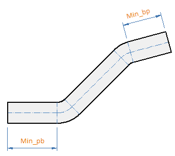
Min_pb = Minimum distance from beginning of pipe to first bend (no flanges).
-
Min_bp = Minimum distance from last bend to end of pipe (no flanges).
-
Min_db = Minimum distance between two bends.
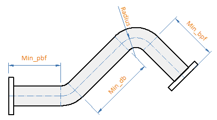
Note: Minimum distances are measured from the gasket surface of the flange when the pipe is bent with a flange or with a pressed pipe end.
Elongation
Plant Modeller considers bend elongation in the cut length. Plant Modeller can use two methods to compute elongation: linear or interpolation from an elongation curve.
Linear
If the dimension attribute 'elong' exists in the bending machine Dimension Table, then the value of that dimension gives the linear elongation coefficient as mm/degree of the bend angle. For example, value 0.1 would give 9 mm elongation for a 90 degree bend.
Interpolation
If a Dimension Table contains dimensions with names 'elong-xx', where xx is a string of digits, then these define points (angle, elongation) along the elongation curve. The digit string xx specifies the angle (degrees) and the value of the dimension gives the corresponding amount of elongation. Elongation for intermediate angles is computed using linear interpolation in the interval that contains the given bending angle. If the angle is not in any of the intervals, then extrapolation using the first or last interval is used. Note that points along the elongation curve must be given in increasing order of bending angle.
Distance to floor
When performing bending checks on pipe spools (see Checks), Plant Modeller can check whether a pipe to be bent will collide with the floor under the bending machine. This check can be performed if the dimension attribute 'BndPln_z' exists in the Dimension Table of the bending machine and the attribute specifies a distance-to-floor value for the given pipe size.
The 'BndPln_z' attribute defines the distance in millimeters from the bending plane to the floor, where "bending plane" refers to the Z coordinate of the center of a pipe when the pipe is locked to its position in the bending machine using a pipe holder of the required size. This distance value can be defined separately for each pipe size in the bending machine Dimension Table, and if the value is 0 the pipe size is not checked for collisions with the floor.

Bending machine object attributes
In the Object section of the Dimension Table, click Attributes to view and edit the attributes that define what kind of constraints the machine imposes on the bending process. In CADMATIC, "tail" refers to the pipe end that is clamped to the bending machine, and "head" is the pipe end that is rolled around the forming die to create the curve.
In the list below, the tag that each attribute uses is shown in parentheses.
-
Description (.dG) – The name of the bending machine.
-
Compute extra lengths for bends or pressed collars (cel) – Select whether to calculate additional pipe length for bends and pressed collars.
-
Maximum Pipe Length (bML) – The maximum pipe length that the machine can handle.
-
Maximum Set Length (bSL) – The maximum pipe length from the tail of the pipe to the bending die.
-
Start Bending At (bST) – Defines which end of the pipe is the head.
- SHORTER – The bending is to start from the end where the distance to the first bend is shorter than in the other end.
- LONGER – The bending is to start from the end where the distance to the first bend is longer than in the other end.
- OPTIMIZE – The bending is to start from the end that results in less piping material being used. (Attribute not used in bending check.)
If the attribute is not defined, the shorter end is selected unless other factors require selecting the longer end.
-
Bending Direction (bDl) – Defines whether the machine bends the pipe to LEFT or RIGHT, as seen from the front of the machine.
-
Bending Machine GDL (.hq) – When the bending machine's Dimension Table has been linked to a GDL that describes the geometric model of the bending machine itself, this attribute shows the object ID of that GDL. This is only required if you want to simulate the bending with a custom script.
-
Bending with Flange (.hx) – Defines whether the bending machine supports or requires bending with flanges.
- Not supported – The machine cannot bend pipes with flanges.
- Supported (default if attribute not defined) – The machine supports flanges, but prefers bending without flanges.
- Preferred – The machine prefers bending with flanges.
- Required – The machine only supports bending with flanges.
Note: Bending with flanges might not be possible if (a) the flange's catalog part, (b) the flange model object, or (c) the bending machine has an attribute that defines welding to be done after the bending, or vice versa.
-
Minimum Pipe Length if Bending with Flanges (.hy) – The minimum pipe length when bending with flanges (if supported by the machine). If pipe is shorter than this value, then it is bended without flanges.
Additional bending machine object attributes
You can define bending machine attributes that only affect the bending process of pipes that have pressed ends or welded flanges. To do this, create COS attributes that refer to a specific bw* tag, assign the new attributes to the "Bending Machine" COS object type, and then add the attributes to the Dimension Table of the bending machine.
Attribute for Pressed Ends
If pipes have pressed ends, a bending machine attribute can specify when the end is to be pressed.
-
Tag:
- bwH
-
Values:
- 0 – End is pressed after the bending.
- Any other value – End is pressed before the bending.
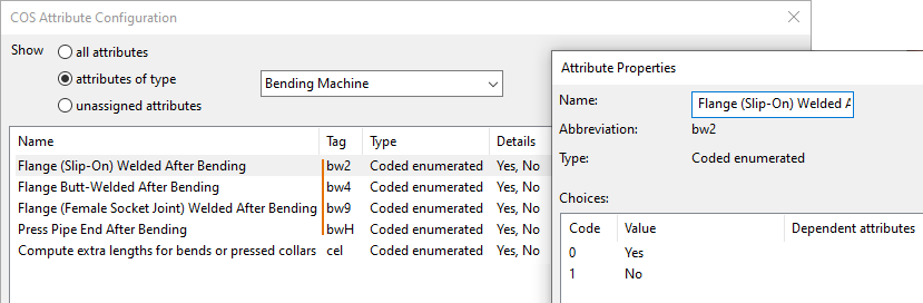
Attributes for Welded Flanges
If pipes have welded flanges, face type specific bending machine attributes can specify when the flange is to be welded.
-
Tags:
- bw2 – For slip-on flange (face type 2).
- bw4 – For butt-welded flange (face type 4).
- bw9 – For flange that uses female socket joint (face type 9).
-
Values:
- 0 – Flange is welded after the bending.
- Any other value – Flange is welded before the bending.
Example Configuration
If these attributes conflict with the normal bending machine attributes, the program reports a problem in bending.
If the bending machine does not have these attributes, the normal bending machine attributes determine the bending process of pipes that have pressed ends or welded flanges.
Cut length calculation
Plant Modeller computes the cut length of pipes when generating material takeoff data or isometry data, and when checking the manufacturability of pipes. The cut length is the length of the straight pipe to be delivered to the bending machine. In material lists generated from isometries, the cut length can include extra length (tags el1, el2) assigned to the piping object in the spool tool of Plant Modeller or in the Piping Isometrics & Spools application.
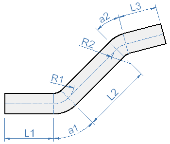
Normally the cut length of a bent pipe (like the one shown in the figure above) is computed as
L1 + R1*a1 - elongation1 + L2 + R2*a2 - elongation2 + L3
where a1 and a2 are bend angles in radians.
For free radius bends (where Plant Modeller has no bending machine info), elongation is always 0.
Extra length calculation
During material takeoff Plant Modeller assigns extra length to bent pipes if:
-
The Dimension Table has the object attribute Compute extra lengths for bends or pressed collars (tag 'cel') set to "Yes" (or other object attributes that affect the calculation).
-
Pipe lengths at the start or end of the pipe, or between bends, are shorter than the minimum lengths required by the bending machine.
If extra lengths are computed then Plant Modeller takes the "shorter" end of the pipe to be the start of bending.
Pressed pipe ends
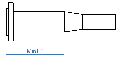
Pressed pipe ends are modeled in Plant Modeller as flanges—the designer adds a pressed collar to the pipe end. The type of the connection face in the Catalog Part must be '17' (Part manufactured from connecting pipe). The backup flange used in the connection must be introduced as a slave part of the pressed pipe end. The length of the pressed pipe end in its Dimension Table is typically measured from the gasket surface to the end of the backup flange (L in the image below), since the backup flange is normally included in the geometric model of the pressed pipe end.
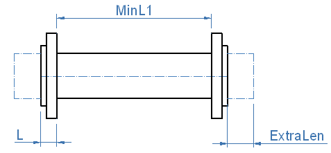
The Dimension Table of a pressed collar must include additional dimensions with names 'ExtraLen', 'MinL1', and 'MinL2'. The cut length of the pipe will include the length of the pressed pipe end and the value of dimension 'ExtraLen'. Minimum free pipe lengths required during manufacturing are specified in dimensions 'MinL1' and 'MinL2'. If the free pipe length is shorter, then extra length will be added. In these cases the pipe ends are first pressed and then the extra length is cut away. In the case of the figure above this requires one extra weld. Extra length due to too short pipes is assigned only if the Dimension Table of the bending machine has the Compute extra lengths for bends or pressed collars (tag 'cel') machine attribute set to "Yes".